
modern undercabinet lighting

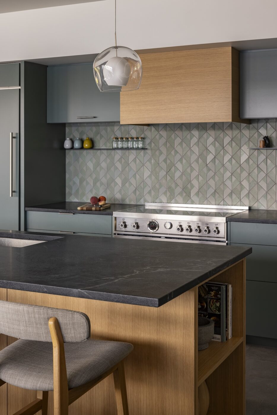
Last weekend we completed the final to-do on the kitchen – installing the undercabinet lighting. We wanted something minimal, yet effective. Luckily, we found both these things in an LED system from ET2 Contemporary Lighting.

Techy! Commonly referred to as LED tape, this thin strip has an adhesive backing so installation is literally peel and stick. The trickiest part was designing the system. Power comes up from the panel in the basement through the wall and into a small transformer in the cabinet above the range hood. From there, connector cords go through holes drilled in the side wall of each flanking upper cabinet and down through the faux chase space that we created using the IKEA blue-gray panel remnants (as seen in this older photo below):

The connector cord then comes down through the bottom of the cabinet and plugs into the LED strip via a small 4-way connector. ET2 sells black metal valances but (shocker) we decided to DIY our own. So Kyle bought simple aluminum angles and built our own version that wraps along the front and exposed edge at the range. (It’s fastened to the cabinet with a few screws. We also applied a thin bead of caulk between the two surfaces to prevent light leakage.)

Next, we adhered the strip (and connector piece shown below)… 

…and attached the connector cord (photo below was taken before we pulled the cord tight and secured it with a couple electrical staples).

We wanted the light (and valance) to be recessed from the face of the cabinet, but out far enough that the light wouldn’t cast a shadow on the steel ledge.

Light Emitting Diodes!

Not only do they provide additional task lighting, but they also serve as a subtle night-light of sorts.

It’s a small detail but we’re pleased with the results. More importantly, this was the last light fixture to be installed. Our house had 3 ceiling fixtures when we moved in, now we have mood lighting.  Love that modern technology.

this and that

This weekend was pretty low-key for us – lots of driving around, buying supplies and finalizing the design for the barn doors. There was also some quality TV time…we just finished season two of Mad Men and its got us thinking about some Sterling & Cooper-esque door colors for chezerbey.

Other things:

1. Bailey McZerbey is a weird dog. But I think he likes the new doorstop! (Yeah, that’s his AKC registered name – we hybridized our last names for him.)

2. Our house was featured on Houzz on Friday! See the tour here.

3. I finally signed up for Twitter…although, I haven’t tweeted yet. But I will! If you’d like to “follow” us, go here or click on the fancy button in the sidebar. It’s going to be riveting…in 140 words or less. (I also added a “tweet this to your tweeps” button at the bottom of each post.)


the loft ladder: process

Most of our undertakings here at chezerbey follow a typical design process. First we brainstorm ideas and sketch things out on paper. Then we test out those ideas in SketchUp. When we’re happy with the design, we detail it out in AutoCad (not always necessary, but it was for a detailed assembly like the loft ladder).

Since we started out sending the design to local steel shops, the drawings were very detailed. After we decided to DIY, Kyle used the shop drawings to accurately measure and cut the various pieces (the design also changed a little bit in between). Unfortunately, I didn’t capture the total construction process. For one, cameras and molten steel don’t really go together. Second, while Kyle was welding, I was holed up in the basement trying to bring order back to the space. After six months as a storage unit and studio apartment it was stuffed to the gills. And then, it threw up on itself. Or at least that’s what it looked like. But that’s another post, back to the ladder!


Kyle started off by cutting the various pieces to size. In the photo above, he’s using a metal cutting saw to cut the steel rods for the lower and upper portion of the ladder.

Next, he used a grinder to bevel the edges of the rods and his drill press to slightly pre-drill the side rails, that way when he clamped it all up for welding it stayed in position.

Once the pieces were cut, the basic frame was welded together. We ended up swapping out tube steel for channels for the side rails. This lightened the overall weight and well, channels are just sexy and cast more interesting shadows. Don’t you think? Next, the rods and treads were installed. The treads had to be a precise angle so when the ladder is in place they would be level with the floor. This was probably the trickiest part of the process.

Kyle also pre-drilled and pre-counter sunk holes in the steel plates so he could later screw the wood treads into place.

I knew the carport would come in handy someday! Here, Kyle is grinding his welds to get a smooth joint.

After the ladder frame was complete, he moved on to the handrail assembly, comprised of 3/8″ diameter rods and 3/4″ square tube steel.

More grinding!

But it really did make a difference…the above shows a good “after” and “before”.

After the ladder and handrail assembly were complete and welded together, it was time to paint. Originally, we were going to have the steel powder-coated. However, we decided that since it’s not exposed to the elements and the steel portions won’t be regularly touched, a simple and durable paint was more than sufficient(and it would save us a considerable amount of money). After trying a half-dozen paints we settled on a dark grey paint used in the auto industry for painting motors. It sprays like a fan instead of a cone (like typical spray paint) so it goes on much more even.

After the paint was dry, Kyle applied a clear coat in a satin finish for a little extra protection.

For the wood treads, Kyle cut 2′-2″ lengths from 5/4×6 vertical grain fir boards (actual size is 1″x 5 1/2″). He then beveled the outboard edge and notched the underside to fit over the steel treads (detailed photo below). Where needed, he chiseled out the underside of the board to fit snuggly over the welds at the joint between the steel channel and plate.

For the handrail, he ran 2×2 fir pieces through the table saw to create the notch. At the bottom of the handrail where the steel ends, he used a chisel and hammer to complete the notch.

Where the tube steel turns 90 degrees and connects back to the channel, he used a small saw and chisel to notch out the wood.

(The photo below shows the completed handrail detail.)

After the clear coat was dry, we moved the steel portion inside and secured it in place with lag screws at the bottom angle and top flat plate (both sets of screws go into structural members so this thing is solid). The angle at the base also covers the exposed edge of the cork flooring. The gap between the ladder and the wall meets code requirements while providing enough space for the future barn door to slide past.


Bailey still doesn’t get it.

All in all, the ladder took about 6 full days of work but we saved a ton of money (even after you factor in the cost of the welding machine). This weekend we’ll apply the finish to the wood. We’re planning on doing a hardwax oil floor finish for the treads and a thinner polyurethane application on the handrails. At the same time, we’ll put the finish on the basement treads and risers (which are partially installed).

The big 2010 project is definitely stretching into 2011, but that’s ok.


the loft ladder

We’ll show the process photos later this week, but for now – the mostly finished loft ladder! (The wood pieces are just dry fitted now, they’ll be removed and taken down to the basement to get finished this week.) It took three of us (thanks Audrey!) to get the steel portion inside and into place, but it’s in.  It was dark by the time we finished up today, so I turned on all the lights and tried to get a few decent shots.

Not a bad way to climb up 9 feet to a 200 sf space, huh? That’s 200 sf of unfinished space too. I’m still boycotting paint.

As the handrail extends up the ladder it straightens out and becomes a guardrail to the light well below. It’s also a good place to grab onto as you climb in or out of the space.

The handrails and treads are wood so that they’re warmer to the touch. The underside of the treads are notched to fit snugly over the steel treads (sub treads?) and will be fastened through pre-drilled holes in the steel plate. The handrails are also notched to fit around the tube steel handrail frame. We chose the inside face as the exposed side, not just because it looks awesome but because as you’re climbing the stairs your hand is more likely to wrap around the outside three edges, so it made sense for those to be wood.

The intermediate rods at the lower half of the ladder are there to meet residential code requirements.

We didn’t think we could have such feelings for a loft ladder, but we’re totally in love.

Steel and wood, you are hereby BFF at chezerbey.


welding time!

A month ago, we showed you our design for the loft ladder. Because welding was an unknown territory for us and we didn’t own the equipment, Kyle put together shop drawings and we sent them to a handful of local steel fabricators. Even though we were introduced to a couple great companies in the process, the estimates unfortunately came back at $3500-$3800 (and that didn’t include the wood work or powder coating). So…yeah. Time to DIY!

So Kyle took a 5-hr beginner welding class, found a great Craigslist deal on a welding machine (it even came with gloves and a helmet!), and got busy. (Even with the cost of the equipment, it was still way cheaper to do it ourselves.) We’re also lucky to have a steel supplier in our neighborhood.

But before he could build the loft ladder, he had to build a welding table. Or rather…weld a welding table. (His instructor recommended this as a good first project.) So right after we got back from the holidays, Kyle cleared out the carport (which is where we’ve been storing lumber, sheet goods, and well…junk), so he could have a protected place to weld. Since our concrete slab slopes, he set-up temporary supports to ensure that the table frame would be plumb and level. The design for the table was adapted from various welding tables that Kyle had googled. The main objective was a simple frame that had a flat work surface with numerous areas to attach clamps to. Kyle then created a 3D model in SketchUp and referenced dimensioned print-outs during construction.

The table frame is made of tube steel, with adjustable casters/legs attached to flat plates welded to the tube steel. I love this photo. I call the green suit his welding onesie.

The tabletop is a series of steel channels welded to the deeper tube steel members below. This allows the pieces that are being welded to be clamped to the table so nothing moves during the process. (Kyle also used a grinder on some of the finished welds, hence the shiny spots.)

(Even though we bought adjustable casters, our slab was sloped enough that we needed to use some steel scraps as shims to get it perfectly level.)

Not bad for a day and a half of work, huh? I know, my husband is a badass. He is also IN LOVE with welding now. He is literally looking around the house for things to weld, which is probably a good thing, considering we already have a lot of wood. But it’s all about the loft ladder now. Oh, and the sliding barn doors? You know we’re redesigning those!